Schematics
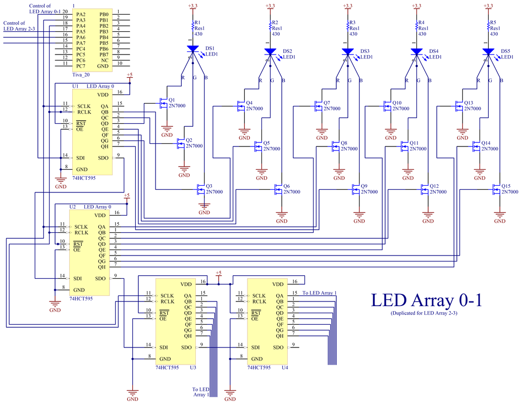
Four identical LED arrays used the above circuit. Each common anode tri-color LED would display the color corresponding to its cathode side when that pin was allowed to conduct current. With five LEDs and fifteen total lines that would need to be controlled for each LED array, two shift registers were designated for each array. To simplify both the circuitry coming from the Tiva and the software implementation, Array 0 and Array 1 used a common shift and register clock. Since the lights only needed to update at a fastest speed of 200 milliseconds, any additional costs in time were negligible.
Note that the wiring for the 15 2N7000 MOSFETs, the 5 LEDs, and the 5 resistors for Array 1 is identical to the ones shown here for Array 0. Similarly, the configuration of the 4 74HCT595 shift registers, the 30 2N7000 MOSFETs, the 10 LEDs, and the 10 resistors for Arrays 2 and 3 is identical to the wiring shown here for Arrays 0 and 1.
Note that the wiring for the 15 2N7000 MOSFETs, the 5 LEDs, and the 5 resistors for Array 1 is identical to the ones shown here for Array 0. Similarly, the configuration of the 4 74HCT595 shift registers, the 30 2N7000 MOSFETs, the 10 LEDs, and the 10 resistors for Arrays 2 and 3 is identical to the wiring shown here for Arrays 0 and 1.
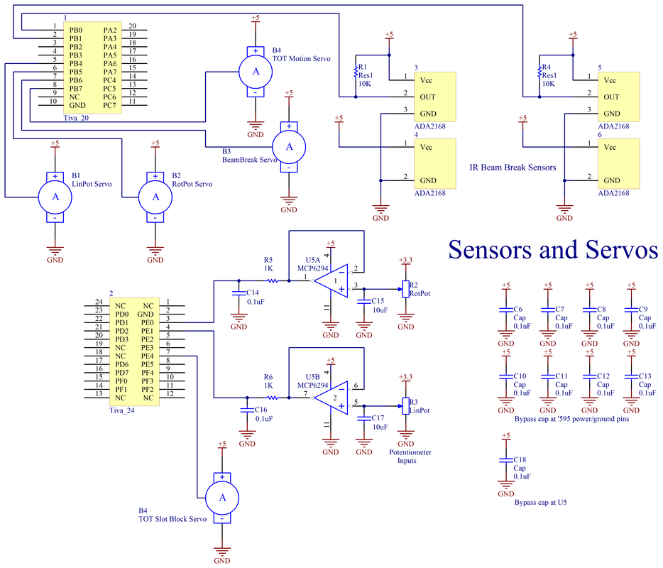
For the shields, three sensors and three servos constituted the player's control. An ADA2168 beam break sends a simple digital signal back to the Tiva—HIGH when the beam is not broken, LOW when it is. The open-collector output requires the Tiva to have digital pull-up enabled. The two potentiometers are read as voltage dividers into the Tiva via analog ports. To smooth these signals, two low-pass filters and two unity gain buffers were used to isolate the potentiometer reading as much as possible. The three servos were controlled using PWM outputs from the Tiva. Note that the servos received +5V from an external power supply, while all other marked +5V sources came from the Tiva board.
Two additional servos and one additional ADA2168 beam break facilitated the TOT's insertion and motion. These servos received PWM control in an identical circuit to the others, and the beam break was read in a similar fashion to the control beam break.
The bypass capacitors for all ICs are shown here. The board-level capacitors are shown in the next circuit. The TOT motion servo also had an additional capacitor across it which will be shown in the following circuit as well.
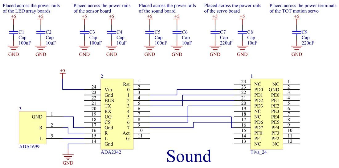
The sound board utilizes two Adafruit components: a sound board and a headphone jack. By using a micro USB cord to connect to the ADA2342 sound board, we placed six audio sound effects (for welcoming state, start-up sound, radiation blocked, radiation missed, game won, and game lost). Upon setting the digital output pins from the Tiva to LOW, the sound will be transmitted out through the L and R pins to the ADA1699 headphone jack.
Additionally, the board-level capacitors are shown here. Using one tantalum and one electrolytic capacitor for each board ensures smooth and reliable signals for all circuits. It is worth noting that the board which maintained the five servos had larger capacitors to ensure smoother servo motion. The TOT motion servo—the one responsible for having the TOT move in the Geiger counter to keep track of time—also had a capacitor across its power terminals to ensure that the motor's motion would not jitter, which was important to make sure the TOT did not fall out of the cup.
Additionally, the board-level capacitors are shown here. Using one tantalum and one electrolytic capacitor for each board ensures smooth and reliable signals for all circuits. It is worth noting that the board which maintained the five servos had larger capacitors to ensure smoother servo motion. The TOT motion servo—the one responsible for having the TOT move in the Geiger counter to keep track of time—also had a capacitor across its power terminals to ensure that the motor's motion would not jitter, which was important to make sure the TOT did not fall out of the cup.
